We will control Christmas lights using relays! I have code that will light 4 strands to the amazing song "Wizards in Winter" by Trans-Siberian Orchestra. We will use relay modules to control power from the wall (120 V AC in the US) to control Christmas lights right out of the box.
This is my third in a set of related projects. It combines the code of the first project and the mains electricity aspect of the second project. Please use the other projects as a reference in case I forget to repeat something on this webpage.
Note to teachers: I would think that students would love to write Arduino code using the free Arduino software then bring the code into a classroom where an Arduino and lights are setup. Having 8 individually-controlled strands of lights strung along the ceiling or wall could be really cool! They can also test their code using their free account at Tinkercad by controlling simulated LEDs with their simulated Arduino. Due to bugs, I do not recommend using Tinkercad to do fancy things like an IR remote or a piezo buzzer.
This project would assess student's ability to write properly formatted code to meet a useful creative goal. I recommend that the use of loops and writing of a code description be required. Perhaps a simple working example can be provided to students.
Warnings: Do not run mains electricity through a breadboard! Also, make all of your mains connections with the power cord unplugged, and use plenty of electrical tape before plugging it in!
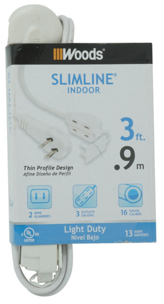
You will permanently modify 4 extension cords such as either shown below. Just be sure that the strands on your tree can be reached, so the cords may have to be different lengths. Perhaps a black cord is the best color?
A suitable cord...
Another suitable cord...

You will need at least 4 strands of Christmas lights. If you want to use my code for a larger tree, you can control more than 1 strand per relay! I prefer LEDs because they turn on and off immediately, do not have an inrush current when first turned on (during the first few ms of being turned on, incandescent bulbs draw over 10 times their normal current), have rich colors, and do not get hot. Though more expensive in the store, they are cheaper over time because they use much less electricity and last much longer. However, if you just love the retro or warm look, then get the old incandescent technology. I can sometimes (rarely!) notice the 60-Hz flicker of LEDs with my peripheral vision, and, if this bothers you for some reason, get full-wave LED lights which have an unnoticeable 120-Hz flicker.
You may instead choose to not use extension cords if you don't need the extra length and instead do not mind modifying the strands themselves (electrical tape can later put the strands back to the way they started). And/or you may also wish to individually control something like 8 strands!
If you want to use the code provided below, you will probably want to buy the MP3 of "Wizards in Winter" by Trans-Siberian Orchestra and have a way to play the song such as a laptop or smartphone.
You need the following to build your control circuit...
• Arduino
• appropriate USB cable for connecting to computer (to initially program it using free Arduino software)
• DC power adapter for Arduino
• SSR module such as this or select the 8-channel one. I haven't actual done this project yet, so maybe this SSR module doesn't work well with Christmas lights! Maybe a contactor relay module is better (certainly cheaper), though a contactor will make a clicking sound, and you really shouldn't do rapid switching with a contactor. Seems like this particular SSR module uses SSR model G3MB-202P, so it is for controlling AC (not DC), is zero-crossing (it will turn on only after the AC reaches 0 V, which occurs 120 times a second in the US, so there may be a delay), and has minimum output current of 0.1 A (though this really means that there is a leakage current up to a couple mA when the SSR is "off", which may not be a problem for LED strands because LEDs completely shut off below a certain voltage).
I was worried about leakage current lighting the LEDs, so I tested this SSR module on a 100 kΩ resistor connected to 120 V AC and then on a 6 kΩ resistor, and both had 0 V across the resistor when the relay is off. However, when there is no resistor and the very-high-resistance meter is the only path for current to flow, I measured 4.7 V. I did some sloppy calculations to get that the SSR could be acting something like a 100 MΩ resistor when off, in which case only a about 2 μA would flow through an LED strand. I was then confident enough to try to power a single bare LED when the SSR is off, and it did not light at all!
When the SSR is on, and current is flowing through either of the resistors, I measure about 0.7 V across the relay, so it seems that the voltage across it is a constant just like a diode. By the way, this is the voltage that can cause an SSR to heat up if there are large currents.
• some male male jumper wires. Female male might be more useful.
• maybe something like an IR receiver to activate the circuit
You will need the following tools (see image below)...
• wire cutters
• wire stripper
• electrical tape
• maybe a soldering iron (and rosin core solder)
• maybe a multimeter
Click to enlarge

There are more tools shown than you need!
We want to connect a relay into each power cord. In the US, the small prong is hot aka live (see image below). Ideally, you want to cut the hot wire of the power cord, but hot or neutral works. Doing hot allows you to do things like change out LEDs safely when the SSR is off (assuming your outlet was wired correctly). Perhaps cut open the power cord to leave just enough cord for the relay to be able to easily rest on the ground next to the wall's power socket. Strip the two new ends of the wire you cut, and twist the strands (optionally use a bit of solder to hold the twist in place). If you cannot figure out which wire is which before cutting, a multimeter and a needle may come in handy! If you cut the wrong one, just solder it back together!
US power socket...
Now connect these two ends to a relay, and be sure to tighten the screws snug to prevent high-voltage wires from flopping around! Before plugging the power cords in, you'll want to add plenty of electrical tape around all the relay terminals. Be aware that you shouldn't touch the screws holding the cord in place, and you shouldn't touch the solder joints on the part of the bottom that deals with high voltage, so tape them up too! You now have finished making a controllable power cord!
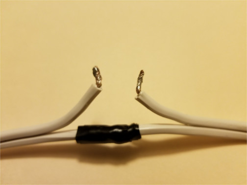
To allow for easier connection to a relay, I actually cut the neutral wire as well so that, after soldering it back together, the neutral wire will be a bit shorter than it had been. I used plenty of electrical tape after reattaching the neutral wire. See below.
A modified power cord...
Connect the relay module to the Arduino using jumper wires.
Here is my code! By default, it uses an IR receiver to activate the code via a TV remote. Or just set the variable receiver = false to have the lighting sequence immediately start. Just update the pin numbers, tell the code whether or note you are using an IR receiver, and find "Wizards in Winter" somewhere, then you can watch the lights sync to the song if you start them both at the exact same time!