Mains electricity is the AC power from the wall. It can be dangerous to work with, but that's what makes it interesting! The goal here will be to control appliances run off of mains electricity using an Arduino.
I will be assuming that you have much of the knowledge from these instructions for controlling LEDs, particularly stuff about transistors.
Warnings: Do not run mains electricity through a breadboard! Also, make all of your mains connections with the power cord unplugged, and use plenty of electrical tape before plugging it in!
You may wish to read about how power grids work.
As is always the case when using an Arduino, keep in mind that it is for prototyping and that it can often be replaced by something else eventually. An Arduino is expensive, bulky, and uses power, so replace it with a smaller circuit if you can. For example, you can use a ATtiny85 (very cheap), though you still have to power it with the correct voltage.
The following will be used permanently...
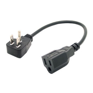
• a short (meter long) extension cord such as either shown below
• a contactor relay that can be controlled using 5 V. Model SRD-05VDC-SL-C will work just fine and is very cheap (shown below).
A suitable cord...
Another suitable cord...
A suitable relay (it's smaller than it looks) that I am using...

You need the following to build your control circuit...
• Arduino
• DC power adapter
• breadboard
• a 1 kΩ or 330 Ω resistor (amount depends on your relay)
• an NPN transistor
• a diode
• jumper wires
• maybe a 5-V breadboard power supply
• maybe something like a sound sensor or IR receiver to activate the circuit
You will need the following tools...
• wire cutters
• wire stripper
• electrical tape
• soldering iron (and rosin core solder)
• some way to connect the relay coil to breadboard such as short pieces of wire connected to 22-gauge solid wire or connected to alligator clips
• maybe a multimeter
I chose the most basic type of relay, a contactor, because that's what came with my Arduino starter kit! However, you may want to consider a solid-state relay (SSR). Here is a great link.
SSRs don't make sound, do not fall apart if doing rapid switching, do not need a diode, last longer, and usually do not need a transistor. They seem perfect! However, there are drawbacks. They are more expensive, you usually need to control it in series with a resistor whose resistance must be calculated, an SSR has resistance so it generates heat and can burn out, you will have to choose between zero-crossing and random-turn-on when purchasing an AC SSR, there is a leakage current even when "off", and the load side often needs protection from voltage spikes (perhaps using a varistor). The complications of an SSR are different from a contactor.
Fading/dimming is difficult even with an SSR. My contactor relay says on its datasheet that I should try not to exceed 30 a minute (or 100,000 in its lifetime), so PWM is out of the question (delay times and AC phase are other complications). SSRs do not have this problem, but, even with a random-turn-on SSR, PWM does not really work with AC because the relay only turns off when the load current is zero. However, it is possible to fade/dim if you can sync the Arduino to the AC phase using AC phase control.
A fancy SSR may allow for dimming/fading. These special control relays will output pulses of full power depending on the voltage they are controlled with. The Arduino does not have a built-in way of changing its output voltage to control one of these control relays, but a DAC could be used with the Arduino to do this.
Another option that I do not consider here is getting a relay module instead of bare relay. The module may have nice things on it like diodes, resistors, and transistors/optocouplers, and you can make connections using screws and jumper wires without needing to solder. These modules may have other complications, so be careful to read about the voltage and current limitations of your model. By explaining how to do the most complicated case of a bare relay, you should certainly be able to simplify the circuit I make to suit a relay module!
Here is how you use a relay module.
Something like this is great to control directly using an Arduino or Raspberry Pi! Many of the complications of an SSR are controlled for in the module, but there will still be leakage current and SSR heating. If you have the money, you should probably get it! Be sure to first do a bit of research to see if it meets your needs.
First, learn about the relay you have. If you have a multimeter and a 9-volt battery, play around with activating the relay and measuring which connections are made!
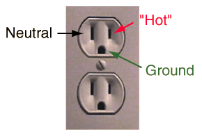
We want to connect the relay into the power cord. In the US, the small prong is hot aka live (see image below). Ideally, you want to solder the common terminal of relay to hot coming from the wall, but connecting it in either direction to hot or neutral works. Cut open the power cord in the middle (or perhaps more towards the end to leave enough cord for the relay to be able to rest on the ground), and cut the hot (or neutral) wire. Solder one of the now exposed ends to the common terminal of relay, and solder the other exposed end of wire to the NO terminal of relay. Every relay is different (mine is SPDT), so just wire it in a way that makes sense! If your relay has a NC terminal, maybe use that one so that the relay will conduct electricity even when disconnected from the Arduino (I prefer off to be the default state, so I used the NO terminal). If you cannot figure out which wire is which before cutting, a multimeter and a needle may come in handy! If you cut the wrong one, just solder it back together!
US power socket...
Before plugging this in, you'll want to add plenty of electrical tape to all the relay terminals. But first, finish soldering the two wires that control the relay's coil. You now have finished making a controllable power cord!
If you're using a relay module, skip down to the code because you don't need a breadboard!
A contactor is controlled by a coil with inductance. This inductance can provide dangerous voltage spikes upon disconnection. To fix this, put a diode in parallel with the coil. An SSR would not need this. Be careful to put the diode in the correct direction to prevent a short circuit!
A diode only lets current flow in one direction...

My relay requires 5 V across the coil to activate the switch. Since the coil has 70 Ω, it draws a bit more than 70 mA. This is too much for a digital output pin of an Arduino, so I need to control this 70 mA with a transistor, and the base of the transistor needs a resistor.
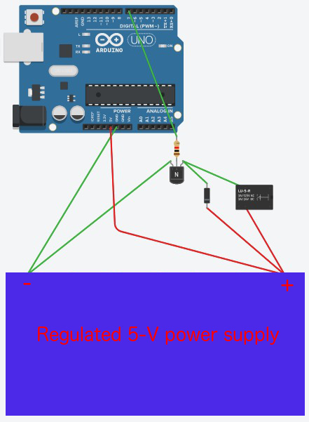
Here is a circuit diagram I made using my free account at tinkercad.com...
For my relay, current in either direction across the coil activates the switch only while the current is flowing.
In the image below, I show my breadboard. If you choose not to use a breadboard power supply, just plug the power adapter into the Arduino instead! The circuit will still work. I prefer to use the breadboard power supply in case I accidentally create a short circuit and because I like to remind myself that the Arduino is for prototyping and should often eventually be removed by some other smaller circuit that uses less power.
Click to enlarge

Here is my code! By default, it uses a sound sensor (model KY-037) to control the power (not shown above). Just clap twice! Or just set the variable soundSensor = false to have the relay simply alternate between on and off every 10 seconds.
If you want to control the Arduino and relay over the Internet, check out my discussion on the very cheap ESP8266! Just take the code in the "Controlling an Arduino" section then...
• in setup(), add a pinMode() to setup the relay pin
• in loop(), add if else statements that control digitalWrite() to the relay pin based on the state variable.
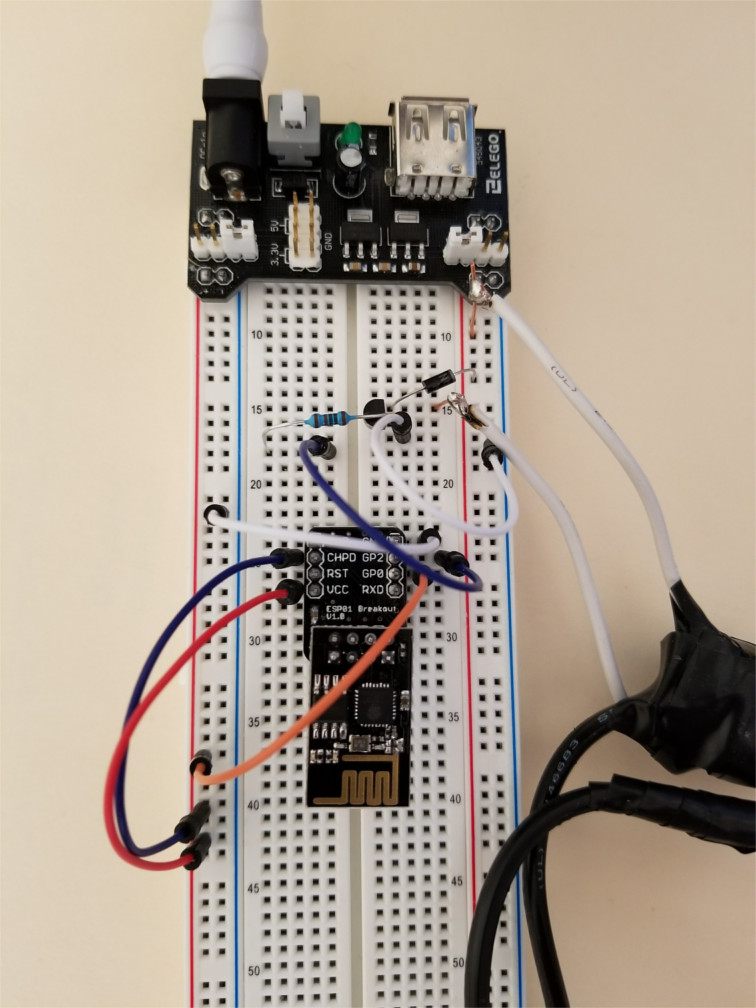
Instead, you may want to use the ESP8266 without an Arduino. I wrote this code for the ESP8266. Just add your SSID and password to the code, then change the state here to control your relay from anywhere with WiFi! However, because my ESP-01 does not have many output pins, I had to use GPIO2, which must not be held LOW on boot. Using GPIO2 as an output pin requires manually disconnecting the relay circuit from GPIO2 when the ESP8266 boots. This is not ideal! A disruption in power that causes the ESP8266 to reboot will prevent the code from restarting.
Click to enlarge