Arduino-Controlled Christmas Lights!
These instructions are for controlling LEDs of Christmas lights using an Arduino! I am not interested in controlling fancy addressable LEDs here because they are bulky and don't really look like Christmas lights. Due to safety concerns, I am also not interested in using relay modules to control power from the wall (120 V AC in the US), which would let us control Christmas lights right out of the box.
For background, please read the end of my coding webpage to learn the basics of what an Arduino can do. You may also wish to read a bit about the history of Christmas lights and the basics of how they work.
I will describe how to do 2 similar projects...
Stranger Things RUN display.
Here is the scene. Here is the full scene. And here is a hilarious parody.
A video of the completed project (using a photoresistor to activate it with my shadow!).
Snowflake that lights to Trans-Siberian Orchestra.
The LEDs will sync to the amazing song "Wizards in Winter". I got my inspiration from this tree. The timing of the code is bit off and does not sync with the music (my code fixes this somewhat), and I loved and copied the "choreography"!
Video of completed project!
Alternatives and Modifications
With a bit of modification (especially of the code), everything can also be done with a Raspberry Pi instead of an Arduino. The Pi outputs 3.3 V from its GPIO pins (Arduino digital pins output 5 V in most models), but that's not a problem because we're just controlling transistors. And the Pi can only be powered by 5 V (whereas the Arduino can be powered by a range of voltages), so the Pi will require multiple power supplies if driving a circuit that needs anything more than 5 V.
My main goal is to explore how a microcontroller can control the external physical world (empowering!), so I prefer the Arduino over the Pi because an Arduino is more about electronics than about software. However, the Arduino has trouble easily and cheaply playing (and recording) music. The somewhat more expensive Raspberry Pi would be needed to perfectly sync high-quality audio with LEDs. With my Arduino in my Snowflake project, I have to manually start the song and the Arduino at the same time, whereas some Pi models have a headphone jack (and HDMI jack) for audio output, and some models have built-in Bluetooth (if not, just connect a Bluetooth dongle), so the Pi can directly control the audio while controlling the LEDs! Note that you can buy a Bluetooth module for the Arduino, but the Arduino is not powerful enough for audio to work, nor does the Arduino normally have an SD card to store music files. However, music can be done, though the quality is limited due to the nature of its digital output (it uses PWM to produce sound waves). There are other ways to sync the song by finding a way to signal the Arduino as soon as the song begins, but you really should get a Pi if you want high-quality syncing.
Even without a microcontroller like an Arduino, you can do cool stuff like fading!
https://www.electronicshub.org/updown-fading-led-lights/
http://www.instructables.com/id/LED-fading-with-a-555-timer/
And blinking can be accomplished using only bi-metallic strips!
Once a circuit has been prototyped with an Arduino, an engineer may then start thinking about how to build the circuit without using a microcontroller (or a small microcontroller like the ATtiny85) to optimize for mass production.
However, since my main interest is controlling the physical world with a microcontroller, which I consider to be a powerful (and not very expensive!) ability, I don't care to explore these options presently. If anything, I would get a Raspberry Pi before exploring this!
An engineer may eventually put all the electronics on the display itself rather than having lots of various wires between the display and the electronics. This way, only two wires are needed (to make a complete circuit for power), or, if a battery is used in the display, no wires are needed! However, I'm not about to build my Arduino into the display partly because the Arduino is a bulky thing for prototyping. However, there is still the question of putting things like resistors and transistors on the display vs. near the Arduino. By putting the resistors and transistors on the display (and also putting a serial-to-parallel converter), 8 LED groups can be controlled with only 5 wires running between the display and Arduino (2 for power, and 3 to control the serial-to-parallel converter). But you then use up your resistors and transistors. Instead, I will choose to put as much of the electronics as possible near the Arduino where I can experimentally put various components into a breadboard to be reused for other projects. This will be especially useful because, unlike mass-produced products that come with a power adapter, my display can be used with different power adapters which would require different resistors. You can build your display however you wish, but mine will put as few electronics in the display as possible.
Planning vs. doing
Whenever I write code or make a design, there are certain big-picture things that can be planned for in the very beginning, and we must do this planning! However, details only become clear at various stages when actually making the code or object. With a vague big-picture idea of the projects I wanted to do, the first thing I did was buy an Arduino starter kit and some Christmas lights, and I borrowed a multimeter. I took apart the lights and played around with everything I could. With this knowledge, I then drew up designs and circuit diagrams, but I did not really think about the details of how to build it beyond what tools I would need. As I learned more by doing and playing around, I could prepare for the next steps, but I would start doing as soon as I could (unless I didn't yet have the tool!).
This incremental process of planning and doing is the only way to approach large projects. My thoughts get wrapped up in loops if I sit around planning every detail because it isn't clear what to do or what will happen. Likewise, I find myself frozen without the correct knowledge and tools if I do not plan first. The feeling of having taken on too large of a project is real and common, so just plan for the next step, then do it. Then repeat!
During this incremental process of designing and doing, a crucial step is testing along the way. Whenever reasonably possible, check that all the LEDs still light up (use a resistor so that the test doesn't make your LEDs fail!). Your sanity will thank you, and you will find problems earlier rather than later. When I did scientific research in graduate school, a phrase I heard from people building an experiment or coding was "plot as you go". If you wait towards the end to see the results plotted on a graph, you will likely see nonsense that is very difficult to untangle.
In this webpage, I have given the big picture and many of the details of how to build the displays. Nonetheless, you may wish to figure out some of these details yourself by actually doing some stuff you've read regarding the basics of transistors, wiring, LEDs, etc. Then read some more. Then do some more. Especially if you are doing your own unique project, I recommend this incremental process. This lesson is true in the professional world as well. Even in the business world, it is better to modify plans as you go than the have the rigidity of an overly engineered plan. Unexpected things will happen! Good engineers don't just sit around making plans without talking with technicians/customers who have the hands-on understanding of how designs are actually implemented. The good engineer then can start working on the next step towards a better design.
In the end, the best part of building something is that—after all the unexpected complications and initial confusion—it actually works! If you are interested and financially willing, the next steps of this incremental process building LED displays would be to go beyond prototyping to make a professional product!
Cost and Preparing
If you don't want an Arduino and basic electrical tools to play around with (use) for a long time, don't buy them! To buy everything from scratch probably costs around $150 (US$). However, once you have (or borrow) an Arduino starter kit and electrical equipment, these projects are cheap. You can construct them both for a total of $15.
In introductory videos or tutorials I find online, I often encounter advice to buy this or that product telling me that I really should buy a good one. While this would be good advice for a professional electrician who should certainly invest in excellent equipment, I assume that we are all beginners here. For beginners, I recommend to buy the cheapest quality because quantity is much more helpful, and cheap quality often is a great teacher. Some examples...
• A crappy cheap car can be the best for an adolescent who then learns how to deal with and fix up the car (and who may wreck a nicer car).
• I borrowed my crappy multimeter from where I work. Once I replaced its corroded battery and used rolled up aluminum foil to replace its blown fuse, it was more than enough for what I needed. I learned that I don't need an expensive meter, and I learned that—if we are careful to obey the max voltages and currents listed on the front of the meter—we can fix blown fuses with aluminum foil!
• I bought the cheapest soldering iron with a copper tip where you could easily scratch off the non-copper protective coating with a screw. After soldering for a few hours, most of the soft copper tip had been dissolved into the solder! I tried replacing it with an iron nail, but I don't think iron has enough thermal conductivity. I learned a lot about soldering-iron tips! If I ever need to do a lot more soldering, I just need to buy a tip, which is much cheaper than the entire iron!
Do not get the idea that cheap is always better for learning because quantity is also great. For this reason, I got a nice Arduino starter kit that came with plenty of toys! No beginner knows what will be needed, so, since shipping costs are usually more than the thing itself, just buy a lot of little things in a nice starter kit!
You'll need to understand the following physics before continuing...
• current (I) is measured in amps (A)
• voltage (V) is measured in volts (V = A Ω)
• ohmic resistors (V = I R) vs. non-ohmic conductors (LEDs for example), where resistance (R) is measured in ohms (Ω)
• AC vs. DC
• DC polarity
• ampere hours (Ah)
• open vs. closed vs. short circuit
• how current and voltage behave in series vs. parallel
• power (P = I V) is measured in watts (W)
If it has been a while since you've taken physics, Khan Academy's circuit lessons should be helpful! Also, OpenStax provides a free physics textbook!
The more programming you know the better! If you know nothing, this is just fine because I will provide the code! You just won't be able to easily understand or modify it.
Knowing how to use a multimeter to measure voltage, current, and resistance should also be helpful! You may not need a multimeter because most things are labeled, but labels may be ambiguous, confusing, or only true under certain conditions. And, when the circuit doesn't work, a multimeter is great for troubleshooting!
You will not need any prior experience building real circuits by hand because the whole point of this webpage is to help you do that!
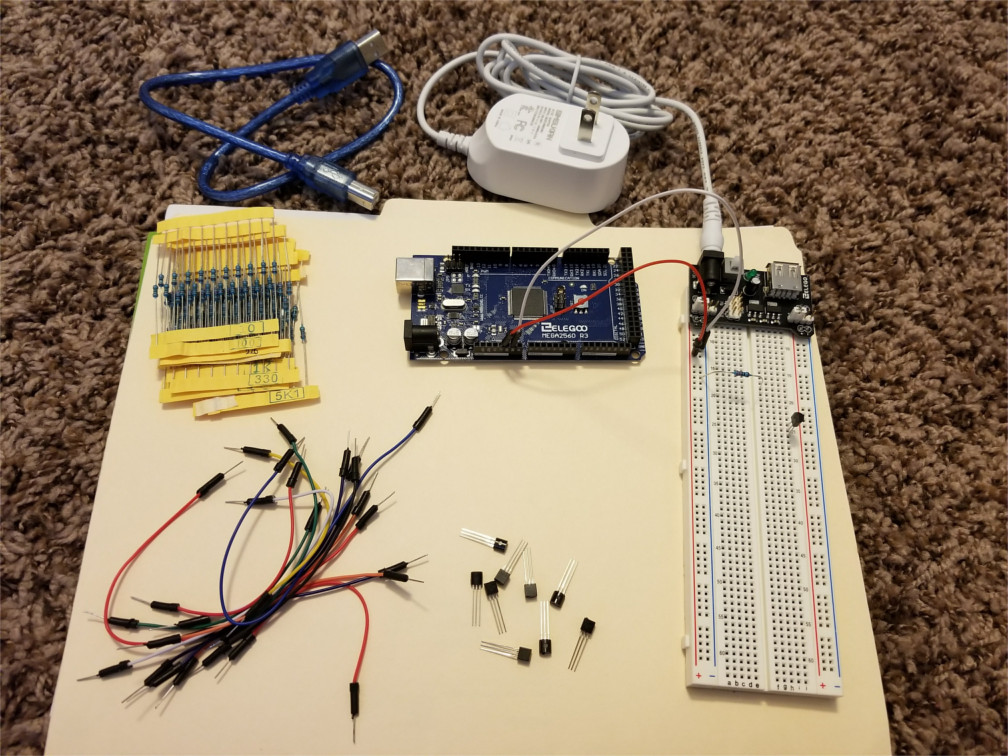
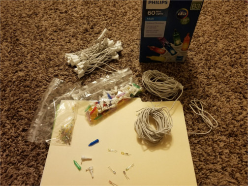
You'll need the following shown in the image below (all came in an Arduino starter kit for me)...
• Arduino! I think any model with at least the capabilities of the Uno should work, even if not the Arduino brand, though it should ideally have 6 PWM pins to do things like fading and 32 kB of Flash (program memory). I got an Elegoo brand starter kit because Arduino was out of stock.
• appropriate USB cable for connecting to computer (to initially program it using free Arduino software)
• 830-tie breadboard (or smaller ones that clip together)
• breadboard power supply module (regulated at 5 V)
• appropriate DC power adapter (make sure that the same one works for either Arduino or breadboard power adapter)
• bunch of jumper wires. Not shown below, a few of them may need to be female male if you want to connect a motion detector or something like this.
• bunch of resistors with diverse resistances
• NPN transistors (1 or 6 depending on which project). For the RUN display, the 1 transistor needs to be able to handle 250 mA as it controls 23 LEDs in parallel)
• maybe a remote, motion sensor, photocell, sound sensor, or something like this for activating the LEDs
Click to enlarge

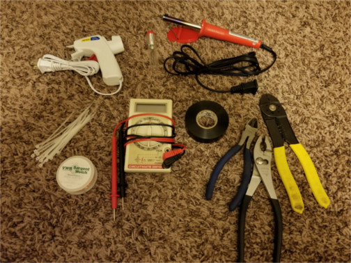
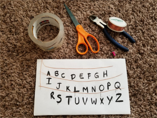
Shown in the image below, you'll also need the following basic electronic stuff for building the displays...
• multimeter (with 2 leads!)
• wire cutter
• wire stripper
• pliers
• solid copper wire with plastic coating such as this. Solid is needed so that we can strip it of the coating and run it along things. I recommend 22-gauge, 24-gauge, or 26-gauge wire (lower numbers are thicker). These all fit into a breadboard so they are generally useful beyond these projects, though the 22-gauge fits best. Thicker is harder to bend, but thinner has more resistance/heat. I know someone who was happy to give me a meter of 22-gauge wire, which also has the advantage of being a good thick wire for soldering other things onto.
• high-temp hot glue gun (and glue!). The RUN display doesn't need this (unless you want to attach the colored plastic over the bare LEDs), but a hot glue gun is cheap and good to have!
• soldering iron (and rosin core solder!). Here and here and here are good videos on how to do it. Maybe try not to breath in too much rosin fumes? And, if your solder contains lead, it is e-waste, so dispose of used or unused solder correctly!
• zip ties are a great way to manage many wires!
• electrical tape might come in handy
Click to enlarge
With all the above obtained, the world is your oyster!
Unlike the above, everything below is specific to each project and may be soldered or glued together preventing it from being reused.
For making the RUN display, you will need something like...
• cardboard
• nail or tack or whatever for punching holes in cardboard
• maybe clear packaging tape for attaching wires to cardboard
• If you don't trust your drawing skills, maybe get some replaceable paper to tape over the cardboard? Maybe use a printer to print out the design?
• basic strand of multi-color LED Christmas lights (can be the same strand used for other project)
For making the Snowflake display, you will need something like...
• 3 popsicle sticks (I cleaned them!). I was too lazy to buy craft sticks. If you want a larger snowflake, maybe use 6 sticks glued to a large flat washer?
• maybe white or blue (spray) paint? I was too lazy&cheap for this.
• basic strand of multi-color LED Christmas lights (can be the same strand used for other project)
• a way to play "Wizards in Winter" by Trans-Siberian Orchestra externally (via a player external to the Arduino)
• an approximately 12-V power supply (I just used a crappy power adapter for an old router that I luckily do not need anymore!) and 2 alligator clips to connect power supply to circuit (or maybe just solder the power supply wires to a the halves of a jumper wire that has been cut in half). You may even be able to find a product like this to not permanently modify your power supply! Or you can use something like this for your car, though I would worry about voltage spikes when starting the car. If the power adapter for your Arduino is no less than 9 V, there is a possibility that you can just use this, especially if you use fewer LEDs!
Wiring basics
• Solid wire is cheaper and more resistant to corrosion than stranded, but stranded gives pliability!
• You can also choose between bare and plastic coated. Plastic is an electrical insulator. You can remove the coating much easier than you can put it back on, so getting coated may be best.
• Breadboard connections want .4 to .7 mm (21 to 26 AWG) solid wire (this is not referring to the coated parts of jump wires, which are stranded). Or, just buy a bunch of jumper wires if you ever need to connect something to a breadboard, then, with 1 jumper wire cut in half, you can solder the halves to 2 things to create 2 breadboard connections!
• https://en.wikipedia.org/wiki/American_wire_gauge
• https://learn.sparkfun.com/tutorials/how-to-use-a-breadboard/
Copper has high electrical conductivity. Because it is cheaper and more pliable than silver, it is commonly used in wires. Gold is also sometimes used for electrical contacts because it does not tarnish, though tin is a more cost effective coating. Copper has a yield strength of 70 MPa, which equals 70 newtons per mm2 or 16 pounds per mm2. So, since 17-gauge copper wire has an area of about 1 mm2, a pulling force larger than 70 newtons (16 pounds) will deform (or even break) the wire. 27-gauge wire is much thinner at 0.1 mm2, so only 7 N (1.6 pounds) is needed to permanently stretch it. Because such thin wire also cannot safely carry much current and is starting to get noticeable resistance, I would never go smaller than 27 gauge.
When connecting electrical components, the following refer to different things...
• + or - refers to voltage. The + means higher voltage, and the minus means lower voltage. You will also see ground (GND) used. This should be used for when the voltage is equal to that of the environment, but, particularly for portable DC equipment like ours, ground just means the lowest (most negative) voltage in the circuit, often called 0 volts so that all other voltages are positive relative to ground.
• Cathode and anode refer to current. A cathode is where positive current leaves a component: the + of a discharging battery or the - of most other things. An anode is where positive current enters a component: the - of a discharging battery or the + of most other things. Note that the direction of positive current is the opposite direction than the direction that the negative electrons flow.
LED basics
Note that an LED is different from any colored plastic that exists around it. The plastic should be clear, or the plastic and the LED should be the same color because LEDs usually only produce a single wavelength, so the plastic cannot let any light through if this wavelength is blocked. Whereas, for colored incandescent lights, the plastic is what actually colors the light by blocking certain wavelengths (not energy efficient). However, I noticed that the red plastic on my lights somehow fluoresces to produce yellowish light when a green or blue LED is put inside, and none of the other plastic does this. For LEDs, the plastic is only there to give the light source some shape for aesthetics and to show the color of the LED even when it is off.
LEDs...
• are better than normal (incandescent) bulbs: longer life, much more energy efficient, turn on and off much faster, less heat, etc., but the initial cost at store is more
• light up only with current going in "forward" direction. The longer of the two leads is the + (anode).
• A voltage larger than about 5 V (depending on color) in either direction can ruin the LED, so electrical resistance in other parts of the circuit is used to prevent this
• Current will not flow until the operating voltage of the LED is reached, then it very quickly increases beyond this voltage (see here). For this reason, think of LEDs as having constant voltage. If an LED receives more voltage than this, it is ruined, so resistor with the following resistance should be used to prevent this!
R = (Vsource - VLED - Vother) / I
where...
I is the desired current (10 mA should be enough)
VLED is the sum of all LED voltages in series with the power supply (depending on the LED color, an individual LED is 2 or 3 V)
Vother is the sum of all other voltages in series with the power supply (for these projects this will be 0 or the voltage across B and E of a transistor)
R is the resistance of the resistor plus any resistance of wires in the circuit
Brightness and eye stuff...
• The eye is most sensitive to green, so green LEDs look the brightest
• If the number of photons of a particular color is doubled, the eye perceives the brightness to be only a single step more (not twice the brightness), so a lot more power is needed to make lights look just a little bit brighter
• Increasing the current beyond 0.01 A does not greatly affect the brightness. In fact, the brightness eventually begins to decrease at very high currents until the LED fails. 10 mA is safe and makes it plenty bright.
Put them in series! (usually)
• Series allows different-color LEDs to have the same current (brightness) without having to put a different type of resistor on each one. However, you can easily do parallel with a single resistor only if all LEDs are the same type and color and there is no hidden resistance from crappy wiring (else only the easiest ones to light—probably the red ones—will light).
• In series, the resistor can be small by putting enough LEDs in series to almost completely balance the voltage from the power supply. However, don't make it too small because it needs to protect against voltage fluctuations.
• I bought a strand of 60 LEDs (powered off of 120 V AC in the US). In the strand, there were 2 strips of 30 LEDs in parallel with each other, so that's 30 LEDs in series! These 30 LEDs require about 75 V, and resistors put 2520 ohms put on each strip of 30. The wiring of these store-bought Christmas lights looks like it has 3 wires (instead of 2) during the sections of 30 LEDs because the "central" wire has all the 30 LEDs connected to it in series. Perhaps this is the typical configuration of store-bought Christmas lights in the US?
• Fancy LEDs (not regular LEDs) may have a shunt in them that allows the current to keep flowing to other LEDs in series even after an LED has failed! In series, LEDs would typically all turn off if an LED fails. In parallel, LEDs would typically get brighter when one fails, which can cause more to fail like a chain reaction. In this case of parallel, a shunt could be used to protect the other LEDs (at high risk of sending too much current through the resistors and transistors in the circuit).
I was playing around with LEDs that came with my Arduino and those in the Christmas lights, and I measured the following voltages across them when on (using 5 V and 220 Ω)...
Red : 2.1 V
Orange: 2.1 V
Yellow: 2.2 V
Green: 2.9 V
Blue: 2.9 V
White: 2.9 V (white works via phosphors in the plastic)
Violet: 2.9 V
When I put them in parallel, the red lit up. Upon removing red, orange lit up. Etc. That is, the above list is in order from smallest voltages to largest (which makes sense considering the photon energy of the different colors!). You will notice that the voltages are either about 2 V or 3 V because of how LEDs are made. I do not have an expensive meter, so I make no promises that the above are very accurate!
However, the above list of numbers can be improved because they do not have constant current. Putting a 330-Ω resistor on the reds, oranges, and yellows, and a 220-Ω resistor on the rest approximately gives the same current through each. When I do this, I get that the reds, oranges, and yellows have 2.0 V, and the greens, blues, and violets have 2.9 V.
Resistor basics
Resistors have a resistance that is approximately the listed value and changes a bit depending on the temperature of the resistor. And they have a power rating (in watts). If a resistor dissipates heat at a power larger than the power rating, the resistor can fail.
For reading color codes on certain resistors, use this chart. It can be impossible to know which side of resistor to start reading from, so just measure it! The resistor must be removed from the circuit when directly measuring its resistance.
Power (measured in watts) of any circuit element is
P = I V
For an ohmic resistor, V = I R, so we get the following complete set of equations...
P = I V = I 2 R = V 2 / R
where V is the voltage across the resistor (rather than applied to the entire circuit) and I is the current through the resistor. You must use units of A, V, and Ω (that is, not something like mA) to get an answer in watts. If P is larger than the power rating of the resistor, do not use the resistor!
If a resistor does not have the correct power rating, you can use multiple smaller resistors in series that add up to the value of the original one. Or, if you know the math of how to find the equivalent resistance when resistors are in parallel, you can use multiple stronger resistors in parallel. Either way, when using more than one resistor, the heat is less for each individual resistor.
The resistors that came with my Arduino starter kit are metal-film resistors, which, unlike wirewound, can be very small, cheap, high resistance, and good for high frequencies due to their small amount of metal. However, wirewound are more stable over different currents and temperatures and have a much higher power rating. Specs for my resistors that came with my Arduino starter kit (seem to be the non-special-order BMW4 on the datasheet I was given)...
power rating: 0.25 W
max working voltage: 250 V
tolerance: 1% (by looking at all the color codes on all my resistors)
I highly recommend that you find these values for your resistors!
As for carbon resistors, they are mostly cheap crap, though they have a slightly higher power rating than metal-film, and they are great for high frequency as long as low currents are used (else noise and instability result from the high currents).
Power supply basics
Arduino power requirements...
• You can power it from the USB at 5 V, but this can be dangerous if not from a well-regulated source such as a computer. Equivalently, you can power the Arduino via the 5V and GND pins, which can be extra dangerous (don't mess up the polarity!).
• For non-regulated voltages, use the DC Barrel Plug 5.5mm/2.1mm (or the Vin pin and GND pin directly if you are careful about the polarity!). Via the DC Barrel Plug (or Vin and GND), the Arduino runs safely on 7 to 12 V, but 6 to 20 V is allowed (whereas a Raspberry Pi has a quite strict 5 V requirement). The Arduino regulates this voltage to 5 V. The power adapter to the DC Barrel Plug that came with my Arduino is regulated to 9V, and can supply 1 A (though the Arduino voltage regulator may not be able to safely take advantage of this 1 A).
• USB can often only supply 500 mA, and the DC Barrel Plug can supply more if less than 9 V. If using higher than 9 V, the Arduino's voltage regulator has to work too hard to safely produce high currents at 5 V. Turning the Arduino on usually takes no more than 50 mA plus whatever you are connecting to it.
• Various pins have various max currents, and pins can be damaged by voltage spikes when directly driving inductive circuits (like motors or relay coils, which can be powered just fine if electric protection like diodes or ICs are used). For driving loads safely, do one of the following...
(1) Use an additional external power supply that powers most things except the Arduino, and Arduino just sends the signals to control transistors. A very convenient additional power supply is the breadboard power supply that runs off of the 9-V adapter that came with my Arduino. The output of breadboard power supply is regulated to 5 V, just like the Arduino output! The Arduino an then be run via USB or whatever to completely isolate it from the dangerous circuit. This may be overkill unless using relays to control a high-voltage additional power supply such as electricity from the wall.
(2) Use just an external power supply using Vin or 5V pins to power Arduino (and using GND pin). This protects the Arduino from large currents, but not voltage spikes, so be sure to protect the Arduino from voltage spikes using another method. Use Vin for voltage higher than 6 V but not much higher than 6 V. Use 5V pin only for regulated protected power supplies that supply 5 V.
(3) Use the normal power supply in DC Barrel Plug then attach your load to the Vin and GND pins to draw up to 0.75 A. Do not draw from Vin while directly powering the Arduino with 5 V. Voltage spikes are still a problem, but maybe less of a problem (regardless, it's good practice to always protect the circuit from voltage spikes). Keep in mind that there is a silicon diode that drops the voltage a bit (by 0.7 V because it's a silicon diode).
• Here's a good read:
https://www.open-electronics.org/the-power-of-arduino-this-unknown/
• Another good read:
https://www.rugged-circuits.com/10-ways-to-destroy-an-arduino/
This isn't what we're using, but let's look at power from the wall (in the US)...
• This is 120 V (rms) with peak voltage at 170 V. This can power LED bulbs, though they will flicker at 60 Hz (whereas incandescent bulbs would flicker at 120 Hz if the time it took them to dim after current is shut off was shorter). You can actually see this 60 Hz flicker if you don't look directly at the lights!
• A single LED and its resistor usually uses no more than 0.00008 kW, which is 0.7 kWh after running for an entire year 24 hours a day, which is about $0.10 ! So a strand should just be a few bucks for an entire year day and night!
• For the sake of safety, I don't want to deal with power from the wall! LED Christmas lights from store are safe because all connections are protected by plastic, whereas anything we do would be more exposed!
Cigarette lighter adapter (in car)...
• These are "12" V, but they actually are more like 14.5 V when the car is running (depending on weather and age of battery), and can spike when starting the car or at other times.
• You can usually draw up to 10 A before blowing the fuse! So no worries here unless you short something due to poor circuit design.
• For $5, you can buy things to power an Arduino or a breadboard, such as this or this.
• Note that you can buy $14 inverters to produce 120 V AC power! I don't want to deal with AC or 120 V, but this is the easiest way to just plug in store-bought lights (without controlling them).
Primary-cell (non-rechargeable) batteries...
• Voltages of most batteries are 1.5 V (though a 9-volt is obviously more!), though they are more like 1.6 V when new
• Resistances are given at room temp (unlike resistors, warmer batteries have less resistance!)
• a 9-volt can do 0.5 Ah and has about 1.5 Ω, so powering 30 LEDs (15 pairs in parallel with each other with each pair getting 0.01 A) has a voltage drop of 0.225 V across the battery and will work for 3.3 hours
• a AA can give out 2 Ah and has about 0.15 Ω, so 3 in series can power 100 LEDs (in parallel with 0.01 A each) with a loss of 0.15 V per battery (4.5 - 0.45 = 4.05 V) for 2 hours
• a AAA can give out 1 Ah
• as for button-cell batteries, let's look at the AG13 battery. It is 1.5 V, has 0.13 Ah and 8 Ω. That is, 3 of these batteries (in series) could power 4 LEDs (in parallel with 0.01 A each) with a loss of 0.32 V per battery (4.5 - 0.96 = 3.54 V) for 3.25 hours. Here is information for other types of button-cell batteries. These are nice for just a couple LEDs like a necklace or little flashlight or something.
• Because the internal resistances and especially the total run time are not great when using batteries, you may wish to consider using more batteries. To do this, you will have to either (1) put groups of batteries in parallel to keep the overall voltage of the circuit the same or (2) put all the batteries in series which will require you to change the wiring of the LEDs. Either way, when doubling the number of batteries, the voltage drop across each bulb due to internal resistance of batteries halves and the total run time doubles.
• You can get battery holders cheap on eBay.
DC power supplies such as rechargeable battery packs...
• The power supply will say the output voltage, max current, and if AC or DC. It will also say the same information for input (from the wall usually), so don't confuse the values for the input with the values for the output!
• The inside of the DC plug is +, and the outside is -. Or there could be a USB plug instead.
• Measure the voltage across the plug with no load attached. If it is higher than the nominal (listed) voltage of the power supply, you have an unregulated power supply. As you draw current, the voltage supplied will decrease. You can use unregulated, but you'll have to measure the voltage while your circuit is running to make the best decisions for things like resistor values, or only use it to power other things that then regulate the voltage to some other value (like the Arduino itself or a breadboard power supply).
• Some regulated power supplies are linear. Others are switching. Don't worry about this for powering LEDs.
NPN transistors used as switches
• Simplest use is as an electronic switch! There are 3 leads on a transistor: collector (C), base (B), and emitter (C). The base produces a small current to the emitter that allows a larger current from collector to emitter to flow. This is a switch because B controls the current from C to E!
• have very fast response times!
• really only works for DC power
• https://electronicsclub.info/transistorcircuits.htm
• https://learn.sparkfun.com/tutorials/transistors/all
My Arduino starter kit came with 5 of each of the following NPN transistors. For both, if the flat side is facing you, the legs are: emitter (E), base (B), and collector (C), in this order.
• PN2222
VCEO = 30 V is the max across C and E
IC = 600 mA is the max through C
minimum current gain (minimum hFE) is 35
• S8050
VCEO = 25 V
IC = 1.5 A
minimum current gain (minimum hFE) is 40
For silicon transistors that are saturated (fully on), there is negligible voltage across C and E, and about 0.7 V across B and E, and hFE does not constrain the current entering C.
The usual way of wiring these with an Arduino is (arrow denotes direction of positive current flow)...
power supply + → Arduino 5V or Vin
Arduino GND → power supply -
Arduino output pin → big resistor → transistor B
power supply + → LEDs and resistor → transistor C
transistor E → power supply -
That is, put the load on the C side (not E), and have Arduino and E share a common ground.
You often have to have a big resistor connected to B else you create a short circuit when turning the transistor on. But, the resistor can't be too big because the transistor needs a bit of current coming from B. The ratio of current coming from C to the current coming from B should be large, but, if there is not enough current coming from B, there cannot be much current coming from C. It depends on the transistor and currents, but maybe make the minimum current gain multiplied by the current entering B to be about 5 times more than the current entering C just to be safe. That is...
IB = 5 IC / (hFE minimum)
However, if driving huge currents through C, you can ignore the above equation and connect a not-tiny resistor to B as long the transistor is saturated.
For making an electronic switch, here are some alternatives to transistors...
• Let's assume that we are powering the display with the same 5 V that powers the Arduino and that we are switching single LEDs. Then, it is easier to switch single LEDs by connecting the LED (with appropriate resistance) directly into a digital pin on the Arduino from the display. This works because the Arduino digital pins can safely run a small amount of current.
• I hear that MOSFETs are better but more expensive than normal (BJT) transistors. You only need them if your power and voltage needs are too high for a normal transistor. Though I hear that high-power transistors exist!
• Relays (ideally solid-state relays rather than contactors) are not needed because we are not controlling high-voltage and high-current (we are not powering entire LED strips!). Unlike transistors, there is complete isolation, so you do not have to worry about base-to-emitter current, and relays can often work with AC.
Let's take apart the Christmas lights!
The spacing between lights is far too large, so we have to rewire it, but we can use the old wires for the new wiring! Just be careful not the cut the wires needlessly. Also, the stupid white plastic holding the LEDs gets in the way, so it will be better to just use the LED with the colored-plastic glued over it (or just use the exposed LED!). Take apart the lights into LEDs, wire, and colored-plastic as shown below. For my Christmas lights, it was a subtle art to use pliers to get the colored plastic off without cracking it (maybe due to these being indoor/outdoor lights?). If you look closely, you can see that the orange LED has a resistor (360 Ω) connected to it by the manufacturer.
Click to enlarge
If you look at some of the photos below, you'll see that using this wire is quite bulky as it's designed to carry large voltages and currents. You may instead wish to buy thinner wire. I would think that using some old telephone wire should also work just fine (if you take it apart, you'll find some thin coated stranded wires), though I would do some research before putting large currents of multiple LEDs through a single wire.
Let's make the RUN display!
Below is a circuit diagram I made using my free account at tinkercad.com. Do not be worried by all the yellow wires because those are all just the wire that you run above the letters of the alphabet. Note that I flipped the transistor around because the leads on Tinkercad were in the opposite order of mine.
Click to enlarge

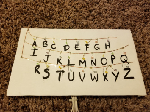
Below is part of a cereal box wrapped in paper. I found the letter design online and printed it. Wires have been attached using tape, and holes have been made using a thumbtack. Try to be careful when taping to leave the appropriate spots exposed so that LEDs can be easily soldered to the wire.
Click to enlarge
Eventually, we will power the breadboard at 5 V using a breadboard power supply, and we will power the LEDs and Arduino from the breadboard. The Arduino will be powered via 5V and GND pins. We will have 10 or 5 wires coming back from the display to the breadboard and Arduino depending on if you want to solder resistors onto the display. Run a wire connected to the + power along the front of the display above the letters of the alphabet. Connect the R, U, and N LEDs to wires that connect to breadboard, then a resistor, and then the Arduino. The current coming from the other 23 letters is far too much to control directly from the Arduino, so use a transistor. I have 6 colors of LEDs, so, for these 23 letters, I wire each color as a group in parallel at the display to be connected by its own wire to the breadboard, so 6 wires (one for each color) will come back to the breadboard to control the 23 letters. Or, put resistors on the display itself so that all the 23 LEDs can use the same wire to connect back to the breadboard).
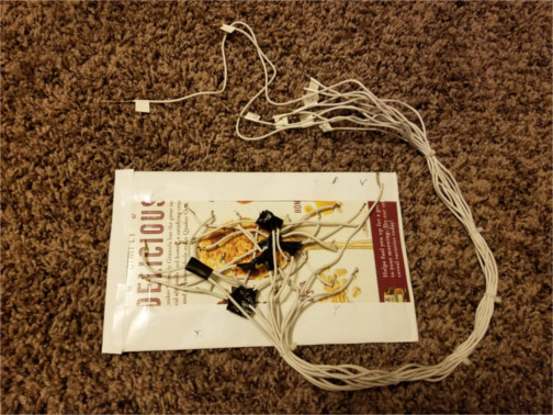
To wire the display, solder the LEDs to the front of the display making sure to have the correct polarity on each. Be careful when soldering to the tiny wires to not burn the display or melt the tape. Then, solder the 5 V wire, the R wire, the U wire, and the N wire. Then do a bunch of soldering of short wires connected to longer wires for the remaining 23 LEDs. Use electrical tape to prevent unwanted connections, use zip ties to manage all the wires, and attach wire that can connect to a breadboard at the end of the long wires. This will take many hours, and you will get much better at soldering! See the following two photos.
Click to enlarge
Click to enlarge
To get 0.01 A going through each LED using an Arduino that outputs 5 V, I calculate the following resistances: 200 Ω for my green R, 200 Ω for my blue U, 300 Ω for my red N, 122 Ω for controlling the transistor, 75 Ω for my group of 4 oranges, 75 Ω for my group of 4 yellows, 75 Ω for my group of 4 reds, 50 Ω for my group of 4 greens, 50 Ω for my group of 4 violets, and 67 Ω for my group of 3 blues. Please check my calculations! Be sure to add up the currents if they are in parallel (there are 3 or 4 mA going through some of the resistors, and there are 23 mA going through C of transistor)! Try not to forget to subtract off transistor voltage when calculating the resistance for B of transistor.
Important. My Arduino's digital output pins can only safely output 30 mA, so, if I use the 122 Ω that I calculated, this will try to draw 33 mA. Luckily, for my transistors, the current gain, hFE, is larger for larger currents through C (up to a point). Also, the 122 Ω was chosen to supply far more current through B than required, so I will instead use a 220 Ω resistor. If I were controlling more than 23 LEDs, I would need to use another transistor to control the transistor, or I would have to use something like a solid-state relay instead of a transistor.
As for actualizing these resistances using the resistors you own, do not worry too much about being exact because 0.01 A can safely be exceeded, though I try to err on the side of less current. To get small values, I used resistors in parallel. For example, 50 Ω is obtained by two 100-Ω resistors in parallel.
Since the human eye is not very sensitive to brightness differences, feel free to aim for something like 5 mA instead of 10 mA through each LED. If you then spread out the LEDs over many Arduino pins (each color group goes to a pin), it can be safe to not use a transistor!
Here is the code needed to control the Arduino. Just update the pin numbers and whether or not you are using something like a motion detector or photocell. Note that, because the wiring was designed with the 23 LEDs behind the transistor in mind, for the Arduino pins that control the R, U and N, we need to set the pin to LOW to light it up, then set pin to HIGH to turn off the LED.
Important? In general, having a device be powered by multiple sources may be a bad idea because currents can start to flow the wrong way through one of the sources. I believe that the Arduino has some ability to switch to the best source, but I've also heard rumors that suggest that the Arduino may not always choose the source that can supply the necessary current. For my sanity, I always disconnect the power from the Arduino's 5V and GND pins before connecting the USB to upload the code, and until the USB is disconnected to reconnect the 5V and GND pins. Even if it doesn't matter in a particular situation, just get in the habit of doing this.
Complications.
• I was wise enough to test the LEDs and their polarity to make sure that I wasn't soldering crap onto my display. I found that 2 of my red LEDs were dimmer than the rest, so I had to change my plans for how many reds to use!
• Various LEDs in my Christmas lights (typically the orange LEDs) had a 360-Ω resistor attached. This is okay for orange and yellow because they need less voltage than a blue or violet. For colors like orange and yellow, this actually gives 8 mA instead of the planned 10 mA. The real issue is that, because I designed the LEDs to be in parallel, I had to be careful not to group an LED that has a resistor with an LED than does not (I don't have any tiny 360-Ω resistors to put onto LEDs that do not have one). I considered cutting off the resistor in case I ever wanted to power the display with less than 5 V (such as 3.3 V), but I figured that the resistor would later make the breadboard part easier, and I didn't want to deal with the remaining nub, so I kept the resistors!
• I labeled all the wires by lighting up the LEDs wire by wire (using a resister to not ruin the LEDs!). Sadly, I wrote O4 twice because I mistook yellow for orange. The O is my way of writing orange, and the 4 is my way of saying that there are 4 LEDs. This was a huge problem because the orange LEDs have resistors connected to them (see the previous complication). So, when I hooked what I thought to be O4 directly to the 5-V power supply, there was a flash then only 1 LED was very dimly lit. I quickly measured the voltage across the dimly lit LED and saw that it was equal to the power supply's voltage. I then knew what had happened and saw that these LEDs had no resistors connected to them, so I had 4 broken LEDs soldered to my display and not enough of any single color to replace them (all 4 had to be the same color due to the parallel wiring). However, I did have 2 yellows (both had resistors attached) and 2 remaining oranges (with resistors). Because they all had resistors and are all yellow or close enough (as opposed to blue which needs a higher voltage), I could group them together. Without trying to be fancy, I just took my wire cutters and removed the old LEDs, and soldered in the new ones. I no longer have spare LEDs of these colors, but it works!
Let's make the Snowflake display!
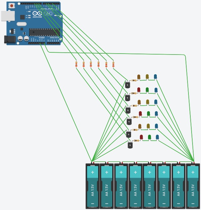
Below is a circuit diagram I made using my free account at tinkercad.com. Note that I flipped the transistors around because the pins on Tinkercad were in the opposite order of mine.
Click to enlarge

We will eventually use the 12 V power supply to power the breadboard, which then powers the LEDs and the Arduino (via Vin and GND pins). There will be 7 wires coming back from the snowflake to the breadboard and Arduino: 1 for the power supply's + and one from each of the 6 arms of the snowflake. You will eventually need 6 transistors and lots of resistors. Design it with left-right symmetry with one of the 3 "axes" being vertical.
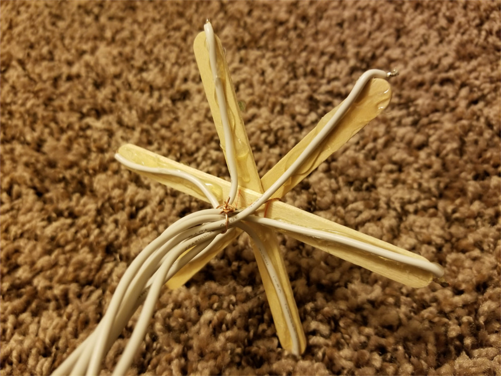
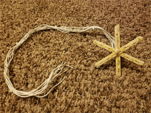
To build the display, print a protractor or use one you already own. Use a ruler (can also be printed) to draw a circle at the center of each of the 3 popsicle sticks, then use the protractor and hot glue gun to construct a snowflake. Glue all the LEDs onto the snowflake. Wrap a wire around the center of the snowflake to serve as a common + connection. Solder the metal connections together. Use hot glue gun and another wire to secure the wires onto the back of the snowflake. Manage the wires with zip ties, and solder solid wire to the ends of the long wires for connecting to breadboard. See the following photos. Not shown is me labelling the back of the top of the snowflake and the ends of the 6 wires from each "arm" using a permanent marker (would have been easiest to do before using zip ties), where the numbering is taken from the comments in the code.
Click to enlarge
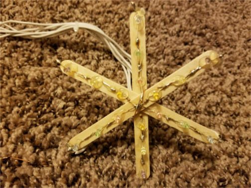
Click to enlarge

Click to enlarge
My unregulated power supply is measured at an average of 15.8 V when powering my Arduino. Because I want 0.01 A traveling through each LED and my Arduino outputs 5 V, I get the following resistances: 800 Ω on each of my three red-green-blue (RGB) "arms" of snowflake, 900 Ω on each of my three orange-yellow-violet (OYV) arms, and 2800 Ω for controlling each of the six transistors. Please reproduce my math given my supplied voltage to make sure that you are doing the math correctly, then calculate the values that apply to your setup.
Do not be worried that half of my power is going into resistors rather than LEDs (seems wasteful!). The amount of total power being used in resistors and LEDs is smaller than what the Arduino needs to run, and even the Arduino uses no more than a few watts of power. You instead may want to worry about powering the Arduino with such high voltage because this wastes a large percentage of these few watts as the Arduino's voltage regulators work to lower the voltage to 5 V.
If you are now worried about the power being used up in the Arduino's voltage regulators, you can reduce this by using two power supplies: one for the LEDs, and another that has lower voltage to power the Arduino. Be sure to disconnect the high-voltage power supply from Vin before plugging in the second power supply! However, do keep the GND pin's connection so that both power supplies share a common ground with the circuit. You may want to seriously consider this option if your power supply provides closer to 20 V than 12 V to protect the Arduino. If you are interested in saving more power, there are many various sleep modes that can be activated if you really want to learn all about the guts of an Arduino. Better yet, just increase the resistances (I used 1000 Ω or 1020 Ω on each "arm" of the snowflake, and 5100 Ω to control each transistor) and use a power supply with a lower voltage.
A final option is to only use the 9-V power adapter that came with the Arduino. This can power the breadboard using the Vin and GND pins. My regulated power adapter measures at 9.1 V, when means that Vin is at 8.4 V. For the RGB arms, I would need 60 Ω each. For the OYV arms, I would need 150 Ω each. However, I have the 360-Ω resistors soldered onto the OYV arms, so this won't work for me without a bit more soldering. These resistances seem too low for my taste as they provide little protection against voltage fluctuations. My personal motivation was to build something that could be powered from a car's cigarette adapter, so I choose to not use the 9-V adapter. This is also the safer choice in case there is a short circuit on the breadboard because I'd rather not risk damaging the Arduino.
Here is the (lengthy) code needed to control the Arduino. Just update the pin numbers, tell the code whether or note you are using an IR receiver, and find "Wizards in Winter" somewhere, then you can watch the snowflake sync to the song if you start them both at the exact same time!
Important? In general, having a device be powered by multiple sources may be a bad idea because currents can start to flow the wrong way through one of the sources. I believe that the Arduino has some ability to switch to the best source, but I've also heard rumors that suggest that the Arduino may not always choose the source that can supply the necessary current. For my sanity, I always disconnect the power from the Arduino's Vin and GND pins before connecting the USB to upload the code, and until the USB is disconnected to reconnect the Vin and GND pins. Even if it doesn't matter in a particular situation, just get in the habit of doing this.
After using the code, if you want to try something a bit fancier, here is code that is setup to do fading. I didn't do anything too fancy. I'd imagine that you could do something really cool with this!
Since I have the display built and connected to my Arduino, I wrote a short code to control the snowflake via a sound sensor! My sound sensor is model KY-037, but I'd imagine that any model can easily be adapted.
Complications.
• Unlike the other project, this one had only minor complications. For example, I bought the wrong hot glue. There were long and short sticks. Since I got the small glue gun (recommended!), I got the short sticks. However, the sticks also have width, and I got the regular width, but I needed narrow.
• Various LEDs in my Christmas lights (typically the orange LEDs) had a 360-Ω resistor attached. I decided to keep them there, but I just had to be sure to remember that they are there when choosing resistors. I used two 330-Ω resistors in series with the 360-Ω resistor to get 1020 Ω for each of my OYV arms.
• The LED leads can snap off if trying to bend them around the ends of the snowflake "arms". To fix the broken leads, I used careful soldering to the remaining nub and generous use of hot glue to hold the wire in place.
What's next?
First of all, I am curious what type of person is interested in doing projects like this. I have a theoretical physics background and wanted to explore the applied side of science and technology, and I would expect any physics or computer-science person to be interested in these projects. I learned a lot about transistors, wiring, soldering, and LEDs! I would expect electrical technicians to be interested perhaps allowing them to learn more about code. I would also expect electricians to be interested in order to explore small-scale electronics. Mostly, I would expect future electrical engineers to be interested (or current engineers if they are looking for an easy project for once!). Lastly, any artisan or maker who wants to learn something technical should have fun. Prove me wrong! If you built these projects, let me know. Please share a bit about yourself, what you learned, and any modifications you made!
The projects we just completed are the first step to something like these! Or, if you have addressable LEDs and a spare wall and a spare computer to dedicate to the task, you can do this RUN display. If you have nothing better to spend your money on, why not?
Probably using addressable LEDs similar to something like this is a more realistic next step. Once you go down down this road of building interesting things, if you're like me, you'll keep seeing more cool things you would like to do like this and this and this!
If you enjoyed doing these projects, consider an electrical, computer, or physics degree!
Or, if you don't need another degree, be like me and think about playing around with robotics or 3D printing one day (via the help of a makerspace)! As a teacher, robotics seems interesting because it is often used to teach various technical skills to students to prepare them for college and the future.
The LED projects on this webpage could also be geared towards students by avoiding the soldering by just using various configurations of LEDs (or an LED dot matrix) and transistors on breadboards. This project would assess student's ability to write properly formatted code to meet a useful creative goal and to apply the fundamentals of circuits and design. I recommend that the following be required: use of loops in code, use of LED groups (in parallel and/or series), writing of a code description, and writing a log/journal of stages of design. Perhaps a simple working example can be provided to students via tinkercad.com.