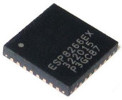
The ESP8266 is a WiFi chip allowing any object to be controlled via your home network or the Internet. For example, you could control an Arduino simply by viewing an HTML file stored on your smartphone or computer. The Internet is an amazing tool, so this chip is very exciting! Shown below, the chip is only 0.5 cm across!
The ESP8266 is a microcontroller just like an Arduino! It can control an Arduino right out of the box, or you can program it to run its own code!
The WiFi of the ESP8266 only uses the 2.4 GHz range (not the newer 5 GHz range). Also, it only uses IPv4 (not the newer IPv6).
Compared to the Arduino, the ESP8266 has less documentation and community support. Highly technical information geared towards developers is available from Espressif, the company that makes the chip, but there is little support for users. Hopefully, my webpage here helps the situation! My goal is a complete discussion of our options and the consequences of what we might do. Most resources online are just people showing off something they did rather than trying to explain how to do anything you want by explaining why they do things. With the basic framework provided here, you should be able to look for specific tutorials and make sense out of them (in this webpage, I also link to some specific tutorials that aren't crap). Trust me, there are a few important gems in this document that are very hard to find elsewhere.
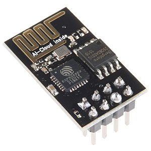
The ESP8266 comes on various modules listed here and here. From this point forward, I will only discuss the cheapest module, the ESP-01 (shown below). It is no more than $4 (USD). All the modules are quite similar due to having the ESP8266 chip, so my entire webpage here can easily be generalized to other modules! Here is a video of a fancy module.
You may wish to read about how the Internet works!
https://en.wikipedia.org/wiki/OSI_model
http://www.informit.com/articles/article.aspx?p=131034
Also, understand that many messages over the Internet are HTTP GET requests over port 80 to serve things like HTML documents. This is how I will communicate to the ESP8266. This tiny little ESP-01 module can participate in the Internet!

Click to animate!
I will assume that you know a bit about Arduino already. I will also give options that do not require the use of an Arduino. Know that most Arduino boards are 5 V, and some are 3.3 V like the Raspberry Pi. The ESP8266 runs on 3.3 V.
For me, the Arduino's goal is to teach and/or provide a flexible way to do a huge number of things. This is why I recommend getting an Arduino starter kit to play around with! My goal for the ESP-01 is different. I just want to control things with the Internet using the cheapest and smallest device that can do the job. In the future, I might get another type of ESP8266 module with access to more pins and a USB port, but I have concluded that the ESP-01 is the path forward for me at this time. Certainly, the ESP8266 is what I want. However, I will here provide some alternatives to the ESP8266.
There are Arduino boards (and shield) with WiFi, but they are typically quite expensive and are not as popular. They typically use an SD card so that they can serve actual low-traffic websites, but why would you use an Arduino to do that? A Raspberry Pi 3 would be a much more natural choice for something like serving an actual low-traffic website. By the way, an ESP8266 module with more pins than the ESP-01 can also connect to an SD card, though it's probably not easy to figure out how!
The Raspberry Pi 3 comes with WiFi (earlier Raspberry Pis can use a USB WiFi adapter to obtain WiFi). It is a full computer running multiple processes/applications and possibly a firewall. People typically use SSH or VNC to control a Raspberry Pi 3 via smartphone or computer. These methods require logging in to the Raspberry Pi. Here is a great showcase of what the Raspberry Pi can do over WiFi! To protect all the different processes and files, computers have lots of protections (such as firewalls and file permissions) to prevent the running of destructive code when messages are received from the Internet. However, you can do whatever an ESP8266 can do by installing an Apache web server then running PHP and using the exec function (you may need to change the user that the runs Apache). Instead, the ESP8266 is a chip that does not have to worry about protecting files or multiple processes and can be devoted to serving your specific task almost right out of the box.
Using a TV remote to control an Arduino or whatever via an IR receiver is easy and cool. But I prefer WiFi because using any smartphone or laptop over WiFi is so much cooler than a TV remote! I want to use a .html file (or app) to control the Arduino from anywhere in the world! I could then have more control than IR by setting a slider to any value. I don't want to worry about exactly aiming a remote at the IR receiver and having to remember to bring a remote with working batteries.
Instead of a WiFi chip, I could use a Bluetooth receiver to control the Arduino such as the HC-05 or HC-06. An app like BlueTerm could then control the Arduino! This video will actually be a good introduction to using the ESP-01 to control an Arduino because the ESP-01 also uses serial communication (TX and RX pins) and 3.3 V. I usually don't like Bluetooth. Bluetooth has limited range (whereas WiFi can connect you across the world!), and Bluetooth cannot easily be controlled by simple .html files instead requiring apps. If you make an app, use App Inventor for Android, and here is a Bluetooth app I made that you can modify (pair a device to your phone before using the app)! The Internet is what changed and changes the world; Bluetooth is just a neat toy. With WiFi, you can access and write information to the Internet (send emails, check the weather, etc.)! However, you may wish to use Bluetooth when controlling a robot that is designed to be near you but possibly far from WiFi (though you can activate a mobile hotspot on a smartphone—with or without mobile data turned on—allowing the ESP8266 to do whatever Bluetooth can do). Unless you want to get very technical, there is no "powerful way" to use the HC-0# like there is for the ESP8266 (described below), and the remaining "easy way" is a bit harder than below because a breadboard is needed to make the voltage divider. Bluetooth has advantages. The Arduino does not need to know anything about an SSID or password (the HC-0# is discoverable immediately upon powering up for the first time), and Bluetooth uses much less power.
If you are using an Arduino and do not really care to ever program the ESP-01 (because you will be programming the Arduino instead), I highly recommend using this! It converts the Arduino's 5 V to 3.3 V, and you just need 4 jumper wires to connect to an Arduino!
As for getting the the ESP-01, for a couple extra dollars, I recommend getting this breakout board plus ESP-01. Who knows, maybe you'll want to program the ESP-01 one day?
You will need some way to connect to a breadboard. The two rows of pins on an ESP-01 are not spaced far enough apart to reach across the central breadboard dip, so you cannot directly connect to a breadboard. Female male jumper wires can work. Or, this breakout board plus ESP-01 is a great purchase because it clearly labels the pins. Do not worry if you end up with an extra ESP-01. They are cheaper than shipping &handling, so err on the side of being too much all in just one purchase.
You'll need a breadboard and jumper wires. The breadboard can be powered by an Arduino, but I recommend getting a breadboard power supply that can simultaneously do 3.3 V and 5 V.
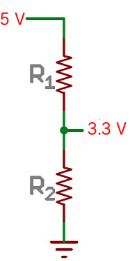
You will want to convert from 5 V to 3.3 V when connecting to the RX pin of the ESP8266. Note that TX pins are held HIGH by default, so you can easily measure the voltage (if 5 V, you need to lower to 3.3 V before connecting it to the ESP8266's RX). To do this conversion, you need a voltage divider by using either a potentiometer or high-resistance resistors. I had a 10 kΩ potentiometer in my Arduino starter kit, but I could not reliably and easily connect it to the breadboard, so I used resistors. To use resistors, you'll need at least two high-resistance resistors with R2 / (R1 + R2) = 2/3. For R1, I used two 1 kΩ resistors. For R2, I used a 5.1 kΩ resistor. So, I get 5100/7100, which is about 2/3! I wasn't trying to be exact (trying to err on the side of more than 2/3 because my Arduino supplies a bit less than 3.3V). I just wanted to use the resistors I have (with large enough resistance to prevent a significant amount of milliamps), while not going over 3.6 V.
If you don't have something like an Arduino, you will need a USB-to-TTL converter (and maybe a USB cable depending on your converter) to connect your ESP-01 to a computer via USB so that you can program it. If you already have an Arduino, it acts as a USB-to-TTL converter! Ironically, if you have an Arduino, you don't need to ever connect it to your computer because you never have to program it (only program the Arduino)! If you don't have an Arduino, there are many options. Do not be fooled into buying this USB thing. The ESP-01 has 2 modes. If the GPIO0 pin is set LOW, it is in programmable mode. If the GPIO0 pin is set to 3.3 V (HIGH), it is in normal mode. The above product does not let you change this setting, so you cannot program the ESP-01 (programming is the whole point of a USB-to-computer connection). Also, the converter feeds 5 V to the RX pin of the ESP-01, which is not safe because the RX pin should receive 3.3 V.
To see an example of how this all could work, this guy built a breakout board and bought a USB-to-TTL converter.
Hook this up to Arduino (for example, using jumper wires)...
GND → Arduino GND
VCC → Arduino 5V
RX → Arduino pin0 (RX)
TX → Arduino pin1 (TX)
The Arduino is now a USB-to-TTL converter! To reset the ESP8266, just power it off then on (using the jumper wire connections or unplugging the Arduino)! See below for how it should look! I added an optional jumper wire from RESET to GND so that the Arduino's code won't run (if Serial.begin() is used in the code, this will prevent the Arduino from acting as a USB-to-TTL converter).
Click to enlarge

Since we are powering the ESP8266 using the 5V pin of an Arduino, there might be concerns given your setup. Unlike the digital pins, the 5V pins of a 5V model (and to some extent, the 3.3V pin) can supply much more current (if you look into this, keep in mind that VCC of the MCU chip is different from the 5V pin!). If you have an atypical Arduino model, maybe you should worry? The real concern is the limits of whatever supplies power to the Arduino. USB can drive at least 500 mA, so using USB to supply power should be just fine. However, if you are using a higher-than-12V power supply, the regulator must work harder to lower the voltage to 5 V, so the current that can be drawn will be less.
Notes on using a USB-to-TTL converter (if not using an Arduino)
If you bought a USB-to-TTL converter that lets you connect the ESP-01 via USB, Linux or Windows work. Mac might also work if you install the right drivers, but USB on Mac is tricky. Note that you can easily make an ESP-01 work with Mac if you have an Arduino!
Notes on using an Arduino
If you plan on controlling an Arduino with your ESP8266, use an Arduino to connect to a computer because you'll need to do all this wiring eventually! Then you never have to buy a USB-to-TTL. I will be assuming that your Arduino uses 5 V. If your Arduino uses 3.3 V, you do not need the voltage divider!
When using an Arduino's pins 0 and 1 as a USB-to-TTL converter, something unique is done. Instead of doing the usual—TX connecting to RX, and RX connecting to TX—you connect TX to TX and RX to RX. This does not seem to make sense. Why would an RX (receiving pin) connect to another receiving pin? Doesn't there have to be a transmitting pin for the receiving pin to have something to receive? It turns out that pin0 is not really an RX pin even though it has RX written on it! Actually, pin0 is the pin that receives from the USB and is actually transmitting that signal. Pin1 is the pin that transmits to the USB whatever it receives. Also, when doing a USB-to-TTL converter, you cannot do Serial.begin() on the Arduino as it prevents pin1 from being controlled by another device's TX pin! Serial.begin() makes pins 0 and 1 be able to be used like any other RX and TX pins (while sending Serial.print() to both pin1 and USB).
Getting the ESP-01 connected to breadboard
To protect the USB-to-TTL converter or Arduino, I recommend using a breadboard power supply (also lets you set 3.3 V easily). If you do, be sure to use a common ground. That is, connect GND of breadboard to GND of USB-to-TTL converter or Arduino. Perhaps the real reason I recommend having a breadboard power supply is that the entire idea of programming the ESP8266 is to eventually not need the Arduino.
Begin by powering your breadboard with 3.3 V and 5 V. If you do not have a multimeter, you can test the 3.3 V and 5 V using the Arduino as a voltmeter! Here is my code to use the Arduino as a voltmeter. By using this code, I confirmed that the 3.3 V and 5 V sides of my supply are accurate and have a common ground! You may wish to turn off the power while making connections.
If your USB-to-TTL converter has 5 V on its TX pin (or if the Arduino has 5 V on its RX pin), make a voltage divider by putting the resistors in series shown below. We do not need to worry about the ESP8266 only sending 3.3 V because this is enough to read as HIGH by whatever is receiving it.
For me, I have R1 = 2000 Ω, and R2 = 5100 Ω. Connect R2 to the - (GND) of breadboard, and R1 will connect to the USB-to-TTL converter or Arduino. Where R1 meets R2 is where you will connect the RX of the ESP8266.
To test the setup, connect R1 to 5 V, then use a multimeter to check the voltages (or use my voltmeter code)!
Component side is facing you in the following image...
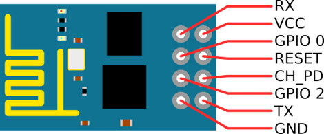
Connect the pins to the breadboard (I use a breakout board)...
Connect ESP-01 GND to - (GND) on breadboard
Connect ESP-01 VCC, CH_PD, and GPIO0 to the 3.3V + on breadboard
Leave GPIO2 and RST open!
GPIO0 pin state at time of boot determines the mode...
HIGH (3.3 V) for running (for example, accepting AT commands)
LOW for programming (and flashing firmware)
CH_PD pin is like an on/off switch, so just always keep it at HIGH (3.3 V).
You can now turn on the breadboard power supply!
Wiring if using a USB-to-TTL converter
I don't have a USB-to-TTL converter, so I won't help you much here. Just read the Arduino section immediately below and figure it out! But connect TX to RX and RX to TX unlike what you do with an Arduino. Perhaps you can ignore most pins on the converter?
Wiring to Arduino
For sanity, upload empty code onto your Arduino (I put in comments on wiring and usage)! The ESP8266 must be disconnected from pins 0 and 1 (or turned off) while uploading the code to the Arduino. Once you are done uploading the empty code, keep the USB cable in so that the Serial Monitor will work. If you do not want to upload a blank code, you can instead just carefully connect Arduino's RESET pin to Arduino's GND pin (shown with a white jumper wire below), which will stop whatever code the Arduino has from running. If the code running on the Arduino does not use Serial.begin(), then you actually do not need to do either of these options, but seeing a jumper wire holding RESET just puts my mind to ease for some reason.
Make 3 connections to Arduino...
• If you are powering the ESP-01 with a breadboard power supply, connect GND of breadboard to GND of Arduino to give them a common ground
• Connect RX of ESP-01 (with voltage divider) to RX of Arduino (pin 0)
• Connect TX of ESP-01 to TX of Arduino (pin 1)
The Arduino is now a USB-to-TTL converter! See below! Note that the part of the breadboard power supply closest to the camera is 3.3 V (other side is 5 V, but I never use 5 V).
Click to enlarge

The easiest and most popular software option is the free Arduino software (Arduino IDE). This can be used without needing an actual Arduino! Open the software. In Tools, go to Port, then select the USB device. Note that Mac will not have the device visible if you do not have an actual Arduino, so it won't work (maybe extra drivers will fix it?). Open the Serial Monitor, and...
• Change line ending to "Both NL & CR". NL is the newline symbol, and CR is the carriage return symbol.
• Set baud rate. 115200 is often the ESP8266 default, but try things like 57600 and 9600 if it doesn't work.
• Now, type and send AT. If you see OK sent back, you did it!
On Linux, a great alternative to the Arduino software (though Arduino IDE works wonderfully on Linux) is to use the screen command...
sudo screen /dev/ttyUSB0 115200
I learned that my USB device was ttyUSB0 by doing the command
dmesg | grep tty
When using the screen command, to send a command, you'll have to do "ctrl+j" after you hit enter. Enter creates a newline symbol, and the "ctrl+j" then makes a carriage return. Also, if you use backspace while typing the command, the command will not work, so this can be frustrating (pasting a command also does not work). Now, type and send AT. If you see OK sent back, you did it!
On Windows, you can also use PuTTY! You can download the putty.exe binary file from the Internet (you don't need the full package, just this file).
First, hit the start key on your keyboard, type Device Manager and hit Enter key.
Look under ports for the COM# of your USB connection.
Run putty.exe. Select Serial, enter the COM# that you found in Device Manager, and enter the baud rate under speed. This works just like the screen command of Linux in that you cannot backspace or paste, and you need to do "ctrl+j" to add a carriage return.
You can now control the module using the following AT commands...
https://www.itead.cc/wiki/ESP8266_Serial_WIFI_Module#AT_Commands
http://room-15.github.io/blog/2015/03/26/esp8266-at-command-reference/
Here are the most useful AT commands for getting you started (doing them in the following order may be best)...
AT+GMR gets firmware version
AT+RST resets the ESP8266
AT+CWMODE=1 sets to client mode (ESP8266 not offering an SSID)
AT+CWJAP="SkynetGlobalDefenseNetwork","password" connects to WiFi (change the SSID and password obviously!)
AT+CIFSR prints IP address
AT+CIPMUX=1 allows multiple connections
AT+CIPSERVER=1,80 turns on HTTP server
All of the above have responses from ESP8266 over serial (RX and TX pins) that terminate with OK.
By doing the above, you can make a web server that listens for HTTP GET requests! Though it won't reply.
By either printing the IP address using AT+CIFSR or logging into your router, get the IP address of the ESP8266. Personally, after my ESP8266 first connects (and is given a random local IP address by router), I set my router's DHCP settings to always assign the ESP8266's MAC address the same IP address so that I never have to look it up again (and to let me use DMZ if I want!).
With the IP address, enter something like the following into a web browser's URL bar!
http://192.168.0.211/?test
Among other text, the extra text "?test" will appear on your computer screen through the Serial Monitor or PuTTY or whatever you are using! This extra text is how you can control things like an Arduino using the Internet!
Or, if you like Linux, here is an example Bash script to signal the ESP8266 then start playing an MP3 file. This is useful because the ESP8266 and even the Arduino cannot play music well (and even crappy music from Arduino takes lots of effort).
     #!/bin/bash

     wget -T1 -t1 -q 192.168.0.211/?wgetTest

     ffplay -loglevel 0 '/home/brad/Desktop/04 - Wizards in Winter.mp3'
On a Mac, you can use afplay to play .mp3 files, and wget can be obtained via MacPorts (or you can use curl).
If you want to use your public (WAN) IP address to control the ESP8266 from anywhere in the world, just turn your router's DMZ to the local (LAN) IP address of the ESP8266. This will forward incoming connections to the WiFi module. If you do this, you may get various "noise" traffic from bots that are sniffing around the Internet.
Here is a simple HTML file I made that lets you control your ESP8266! Mine is better than the crap I found online because mine (1) works, (2) works with touchscreens, (3) only uses AJAX rather than also using jQuery, forms, and other complications, and (4) has a "Requested URL" section. To suit your unique needs, just change url in the <script> block, and of course change the <body> part! Or, just use use the webpage as is! If you do modify it, you do not need to put the .html file online. Just save your .html file to your Wifi-or-Internet-connected smartphone or computer, and open it!
Here is a another HTML file I made that lets you control your ESP8266-powered robot!
If you also want to now start a connection and make a HTTP GET request, you can do something like this (replace the IP address with whatever address should receive your GET request)...
AT+CIPSTART=4,"TCP","192.168.0.200",80 starts connection (will close after a certain amount of time)
AT+CIPSEND=4,9 starts to wait for request of given length (length should be length of following command plus 4)
GET / gives the HTTP GET request (you have to send a blank request following this one)
If the request is successful, you will see the response, and the connection will close! You may also ask for particular webpages such as GET /test.html, but be sure to change the length when doing AT+CIPSEND! To find out the IP address of a website, you will need a DNS service such as this.
We will use the Arduino software to do this (though there are other ways).
Do not program the ESP-01 if you want to communicate using AT commands. Whatever programming you give will replace this interface.
Honestly, I don't recommend that you program it. If you had a module with many more pins than the ESP-01, then the idea is to program it like you would program an Arduino. But the ESP-01 and an Arduino can do so much with just the AT commands we've already been doing. However, I here provide some basic programming instructions so that we can completely understand how the ESP8266 works.
Do the following in the Arduino software to give the software the ability to program the ESP8266 (only have to do this once)...
• Preferences → Additional Boards Manager URL
http://arduino.esp8266.com/stable/package_esp8266com_index.json
• Tools → Board → Boards Manager
search for ESP8266 and install it!
In the Arduino software, select the correct settings...
• Tools → Board
select Generic ESP8266
• Tools → Port
select your USB device
Start with the same physical setup as you used to initially play around with the USB connection. To enter programming mode, switch GPIO0 to LOW. It must be set LOW when ESP-01 boots; once code starts running, it's too late.
If you are using an Arduino for the USB connection, you will also have to, if not already done, carefully connect Arduino's GND to Arduino's RESET. This is necessary to prevent the Arduino from getting programmed with code intended for the ESP8266. I have not personally tested what will happen if you do not do this...
Here is a great video of the above steps! He loads the uploads the Blink example code from
File → Examples → ESP8266
If the Arduino software cannot sync with the ESP8266, there are lots of things to try. I notice that some people put various resistors and capacitors on their breadboards. The first time I programmed my ESP8266, everything worked just fine. A week later, the exact same setup wasn't working (though it would work about 5% of the time)! I got a hint online that adding a 10k resistor between GPIO0 and GND should fix it. I used a 5100 Ω resistor that I had, and everything worked! Let me know if you understand why this fixes it! I feel that I shouldn't have had to do this. Seems like some engineer designed something poorly...
To use it like an actual microcontroller, let's take the Blink example code and change "LED_BUILTIN" to "2" for GPIO2. This pin can only output a max of 12 mA, which is enough to power a single red LED connected to a 220 Ω resistor! If you have a resistor and an LED, hook them up in series being careful of the LED's polarity! Be sure to complete the circuit with ground.
If you want to host a website select the HelloServer example code from...
File → Examples → ESP8266WebServer
Just change the SSID and password! Now you can access your website from putting the ESP8266's IP address into a web browser!
Undo the damage!
It is now time to put it back to the way it started when we bought it! To do this, we must update the firmware using a tool (not the Arduino software)! You will also need to download the firmware! Do not change any of the pins (Arduino still locked in RESET, GPIO0 to LOW, etc.). Doing this may change your MAC address, so, if you set your router settings, you may need to fix your router settings.
The official way is to get the Flash Download Tools here (only works on Windows) and get a Non-OS firmware SDK here (download the ZIP file). I found some overly complicated instructions that used version 2.0.0. What you should do...
• open the tool (run the .exe file)
• put in the COM# and baud rate
• add .bin binary files (from the bin folder in SDK download) and addresses to the tool (make sure to check the boxes next to the binary files)
• select "SpiAutoSet"
• restart the ESP8266
• then start upload
Setting the .bin files is the hardest part. The trick is to hover your mouse over where the .bin files go. A context menu will temporarily appear. Take a screenshot so that you can study it. My ESP-01 has 1MB (8 Mb) of Flash, so I put the following bin files in the following locations...
boot_v1.6.bin                     0x00000
at/512+512/user1.1024.new.2.bin   0x01000
blank.bin                         0x7E000
blank.bin                         0xFB000
esp_init_data_default.bin         0xFC000
blank.bin                         0xFE000
If using a later SDK version (such as 2.2.0), don't blindly use the above list. Use the .bin versions that are the highest.
FYI, there are lots of other tools and firmwares! But going down that road can be a real mess.
We will be talking to the Arduino using the serial (TX and RX) pins. Unlike before, we now do the usual setup: TX to RX and RX to TX.
If you programmed the ESP8266, you should...
• reset the ESP8266 firmware because the codes I provide here use the AT commands
• get rid of the RESET to GND connection on the Arduino
• switch GPIO0 to HIGH on your ESP8266
A few Arduino models such as the Mega have three extra serial ports in addition to pins 0 and 1. If you have an Arduino Mega, the easiest thing to do is connect the serial pins of ESP8266 to Arduino like this...
ESP8266 TX → Arduino Mega pin 15 (RX of Serial3)
ESP8266 RX → voltage divider → Arduino Mega pin 14 (TX of Serial3)
Here is my Arduino-Mega code to test the WiFi connection. It is setup to respond to this webpage (if not using this webpage, just change the main loop of Arduino code). The information sent over WiFi will be displayed on the Serial Monitor. You can put an HTML file like this on any Wifi-or-Internet-connected smartphone or computer!
If you do not have an Arduino Mega, I do not recommend using pins 0 and 1 to communicate to the ESP8266. If you do, you cannot print replies of AT commands to Serial Monitor! An ESP8266's reply to an AT commands contains the command itself, so the code will get stuck in an infinite loop. This means that you cannot print the IP address to Serial Monitor or easily be informed of anything. Though perhaps sending ATE0 to the ESP8266 might help the infinite loops? Regardless, you will have to unplug the ESP8266 serial pins before uploading the Arduino code (or just turn off the ESP8266).
Instead, use the SoftwareSerial library, which lets you use almost any pair of Arduino pins as a serial port. A drawback here is that it can interfere with complicated code because software (not hardware) is running the serial port. Also, you will probably need to permanently lower the baud rate via the first of the following (the second command provided for when you want to change back!)...
AT+CIOBAUD=57600
AT+CIOBAUD=115200
If the above doesn't work with your ESP8266 firmware (gives ERROR), then try one of the following...
AT+UART=57600,8,1,0,0
AT+UART=115200,8,1,0,0
Do not use AT+IPR as there are rumors that this can brick your ESP8266.
To use SoftwareSerial, connect the serial pins of ESP8266 to Arduino like this...
ESP8266 TX → Arduino pin 10 (RX)
ESP8266 RX → voltage divider → Arduino pin 11 (TX)
Here is my SoftwareSerial code to test the WiFi connection. It is setup to respond to this webpage (if not using this webpage, just change the main loop of Arduino code). The information sent over WiFi will be displayed on the Serial Monitor. The code has only been slightly modified from the Arduino Mega's code. You can put an HTML file like this on any Wifi-or-Internet-connected smartphone or computer!
What we really want to eventually do when using an ESP8266 is read data from the Internet and control something based on that. Or, have a sensor that uploads to the Internet (sends an email or text for example). Here is an example! Have fun!